ADDITIONAL NOTES
Wiring when for when you have two contacts to tie into the reset relay.
The control safety is on terminals 3 & 4. The normally closed (NC) control switch represents the relay in the restaurant system control head. You’d have to wire that in series with another closed switch on the flow sensor. In the attachment, I show the simplified wiring diagram with two closed switches. The two closed switches represent devices that are in their usage states (powered on, energized, etc.), not their off-use states. In this diagram, if either of the devices go off-normal, the relay will de-energize the valve.
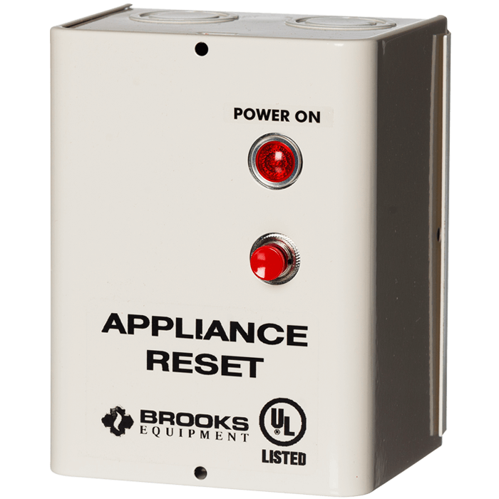
If two (or more) devices that are being shut down are on the same circuit, you can do it from the SRR directly. If the devices are powered from different sources, the output (Terminal #1) of the SRR would need to be considered a trigger and contactors (relays) would be used to switch power to the devices. Terminal #1 of the SRR is “hot” once the Kitchen Suppression System is reset (which provides a closed circuit between #3 & #4) AND the manual reset button is pressed. This is the “normal” or non-alarm state. Activation of the system opens the connection between #3 & #4, removes power from Terminal #1. No power on #1 is the “alarm” state.